The SG90 micro servo is one of the most popular hobby
servos used in robotics and automation projects. Here are its key details:
Weight:
~9 g (very compact and lightweight).
Operating
Voltage: 4.8–6.0 V.
Current
Draw: ~100–250 mA under normal load, higher at stall.
Rotation
Range: ~0° to 180° (limited by internal mechanical stops).
Control
Signal: Pulse width modulation at ~50 Hz.
1
ms pulse ≈ 0°
1.5
ms pulse ≈ 90°
2
ms pulse ≈ 180°
Wiring:
Red
→ VCC (5 V)
Brown
→ GND
Orange/Yellow
→ Signal (Arduino digital pin)
This servo is widely used in robot arms, pan-tilt camera
mounts, RC planes/cars, and small automation projects because of its low
cost and ease of use.
How to
connect SG90 Motor to Arduino Uno
Wiring connection
SG90
Red (VCC) → Arduino 5 V (or external 5 V supply for stability).
SG90
Brown (GND) → Arduino GND.
SG90
Orange (Signal) → Arduino Digital Pin 9 (commonly used).
Tip: If you plan to use multiple SG90 servos or apply
load, use an external 5 V supply with sufficient current capacity, and
connect its ground to Arduino’s ground.
Programming
SG90 with Arduino Uno
Arduino provides a built-in Servo library that
simplifies control. Below are two common examples:
1. Sweep
Example (basic test)
#include
<Servo.h>
Servo myServo;
void setup() {
myServo.attach(9);
// Signal pin connected to D9
}
void loop() {
for (int angle = 0;
angle <= 180; angle++) {
myServo.write(angle);// Move to
angle
delay(15);// Small delay for smooth motion
}
for (int angle =
180; angle >= 0; angle--) {
myServo.write(angle);
delay(15);
}
}
Output: This moves the servo back and forth across its full range.
2. Potentiometer
Control (manual angle)
#include
<Servo.h>
Servo myServo;
int potPin = A0; // Potentiometer connected to analog pin A0
void setup() {
myServo.attach(9);
}
void loop() {
int potVal =
analogRead(potPin);// Read
0–1023
int angle =
map(potVal, 0, 1023, 0, 180); // Map to 0–180°
myServo.write(angle);
delay(10);
}
Output: Turning the potentiometer knob sets the servo angle.
How It
Works with Arduino
The
Arduino generates a pulse every 20 ms.
The pulse
width (1–2 ms) tells the servo what angle to hold.
The
SG90’s internal control circuit compares the shaft position (via
potentiometer feedback) with the commanded angle and drives the motor
until they match.
This
closed-loop system ensures precise positioning without external
sensors.
Practical
Tips
Use
external power if servo jitters or Arduino resets.
Add
capacitors (100 µF–1000 µF) across supply rails to smooth current
spikes.
Avoid
forcing rotation beyond 0–180°; it can damage gears.
Mount
securely using provided horns and screws for stable operation.
Hello Friends, in this blog we will be controlling digital output with serial monitor command.
First let’s understand the working of serial monitor.
Serial monitor in Arduino IDE is a tool which allows communication between the computer and Arduino board via a serial connection, normally we use USB cable for connection.
What are the features of Serial Monitor?
It shows the data sent from the Arduino board by using the functions like Serial.print() or Serial.println().
It allows to send text or numeric data to the Arduino board, which can be read by function like, Serial.read() or Serial.parseInt(), thereafter you can use this data for further analysis and action.
We can use this tool for debugging and monitoring the function of the sketch.
There is a procedure to use the serial monitor, below are the steps given.
First initialize the serial communication in the sketch as given below. Normally baud rate is set 9600.
Void setup(){
Serial.begin(9600);
}
Data can be printed on the serial monitor as the below way
Serial.print(“Arduino is Good”);
It prints the data to the monitor.
Serial.println(“Arduino is Good”);
It prints the data to the monitor with new line.
Reading of the data can be done like the following steps.
If(Serial.available()>0){
Char input = Serial.read();
Serial.print(“You typed: “);
Serial.print(input);
}
Serial Monitor window can be opened by clicking to the Serial Monitor Icon on the top-right side of the Arduino IDE or just go to Tool > Serial Monitor.
Check the baud rate, it should be as same as you set in the sketch during initialization of serial communication. (9600).
Now we will write the sketch for controlling one digital output and also print the status on serial monitor.
// It defines the pin for the digital output, pin 2 is used
const int outputPin = 2;
void setup() {
// Initializes the digital output pin
pinMode(outputPin, OUTPUT);
// Initialize the Serial Monitor
Serial.begin(9600);
Serial.println("Send OUT1_ON to turn ON, OUT1_OFF to turn OFF");
}
void loop() {
// Checks if data is available on the Serial Monitor
if (Serial.available() > 0) {
// Reads the incoming command
String command = Serial.readStringUntil('\n');
command.trim(); // Removes any whitespace or newline characters
// Handles the commands
if (command == "OUT1_ON") {
digitalWrite(outputPin, HIGH);
Serial.println("Output 1 turned ON");
}
else if (command == "OUT1_OFF") {
digitalWrite(outputPin, LOW);
Serial.println("Output 1 turned OFF");
}
else {
Serial.println("Invalid command. Use OUT1_ON or OUT1_OFF");
}
}
}
After writing the code and compilation, upload it to the Arduino board, (I am using Arduino UNO)
Test the code
Open the serial monitor, and ensure the baud rate is 9600.
Send the command OUT1_ON, "Output 1 turned ON") should be printed to the serial monitor.
Send the command OUT1_OFF, "Output 1 turned OFF") should be printed to the serial monitor.
Hi Friends, this is a Game, Escape Lane, made with Arduino. You can name it as per your wish😊
In this game an obstacle comes from the right-hand side towards the character, character has to avoid the obstacle to remain in the game.
In this game I tried to give a human like shape to the character, you can try something else as per your wish
As the game advances, score increases accordingly.
When the obstacle hits the character, game is over, and it asks to start the game by pressing Pin-12
Material Required
1. Arduino UNO: 1 No.
2. 16x2 LCD Shield: 1 No.
3. Toggle Switches or Push Button: 2 Nos.
4. Some Wires
5. USB Cable to Program
Game Working
1. LCD shield is plugged in to the Arduino UNO
2. Input-12 is used to start the game
3. As game is started, obstacle starts coming from the right-hand side toward the character
4. Input-2 is used to control our character, up and down
5. There are two rows, with the help of this switch we can control the position of the character
6. When switch is OFF then character will remain in top row, when switch is ON then it will jump to the bottom row to avoid the obstacle coming towards it
7. On the right-hand side, there is the score counter
Code
/*
* Project: Escape Lane Game in Arduino
* Author: Deepak Sharma
* Date: 11 Aug 2024
* Description: This program uses an Arduino Uno with an LCD shield to make a simple game, obstacle avoidance; name: Escape Lane.
* Version: 1.0
*/
#include <LiquidCrystal.h>
// Initialize the LCD with the pins connected to the LCD shield
LiquidCrystal lcd(8, 9, 4, 5, 6, 7);
// Define the button pins
const int rowControlPin = 2; // Pin to control human row (INPUT_PULLUP)
const int startButtonPin = 12; // Pin to start and restart the game
// Custom characters for the human figure
byte head[8] = {
B01110,
B10001,
B11011,
B10001,
B01110,
B11011,
B01010,
B01010
};
// Game variables
int humanRow = 1; // Initial row of the human figure (0 or 1)
int gameStarted = 0; // Game start state (0 = not started, 1 = started)
unsigned long previousMillis = 0;
unsigned long scoreMillis = 0;
const long interval =100; // Speed of the game (ms)
const long scoreInterval = 500; // Scoring interval (ms)
int obstaclePosition = 12; // Initial position of the obstacle
int obstacleRow = 1; // Row of the obstacle (0 or 1)
int score = 0;
void setup() {
// Set up the LCD and buttons
lcd.begin(16, 2);
pinMode(rowControlPin, INPUT_PULLUP);
pinMode(startButtonPin, INPUT_PULLUP);
// Create custom characters
lcd.createChar(0, head);
lcd.setCursor(0, 0);
lcd.print(" Welcome To ");
lcd.setCursor(0, 1);
lcd.print("ElectroMech Lab");
delay(2000);
lcd.clear();
lcd.setCursor(0, 0);
lcd.print("Welcome To Game");
lcd.setCursor(0, 1);
lcd.print(" Escape Lane ");
delay(2000);
lcd.clear();
lcd.setCursor(0, 0);
lcd.print("Press Pin 12 to");
lcd.setCursor(0, 1);
lcd.print(" Start Game");
}
void loop() {
// if the start button is pressed
if (digitalRead(startButtonPin) == LOW) {
if (gameStarted == 0) {
startGame();
}
}
// If the game has started, proceed with game logic
if (gameStarted == 1) {
unsigned long currentMillis = millis();
// Update the game state
if (currentMillis - previousMillis >= interval) {
previousMillis = currentMillis;
// Move the obstacle
obstaclePosition--;
if (obstaclePosition < 0) {
obstaclePosition = 12; // Reset the obstacle position
Arduino is a hardware & software based platform, which gives
a great opportunity to the hobbyist, students to learn and create interesting
projects.
However, by being expert with Arduino you can make advance projects
as well.
In this article I am going to discuss about delay and millis()
functions.
When we can use these functions to generate delay.
What is the millis() & delay() function in Arduino?
This function gives
the time value in milliseconds since board was started.
Advantage of using
this function is program does not stop during delay.
Other task continue to
take place.
While if you use ‘delay’
function, then program is paused for the time set in delay function.
For example. If I use
delay (5000)
Then program will be
paused for 5000 milliseconds or 5 seconds.
To save the value of millis(),
you should use variables of ‘unsigned long’ type because the value is in
milliseconds and it increases very fast.
For example.
unsigned long current_time
= millis();
While, to use the ‘delay()’
function, you just need to put a value as argument in delay() function parenthesis.
For example
delay(1000);
It creates delay of
1000 ms or 1 second.
You can use delay()
function for delay when, the delay is very little or only single task is being
performed, so that other task cannot be impacted due to this delay or pause.
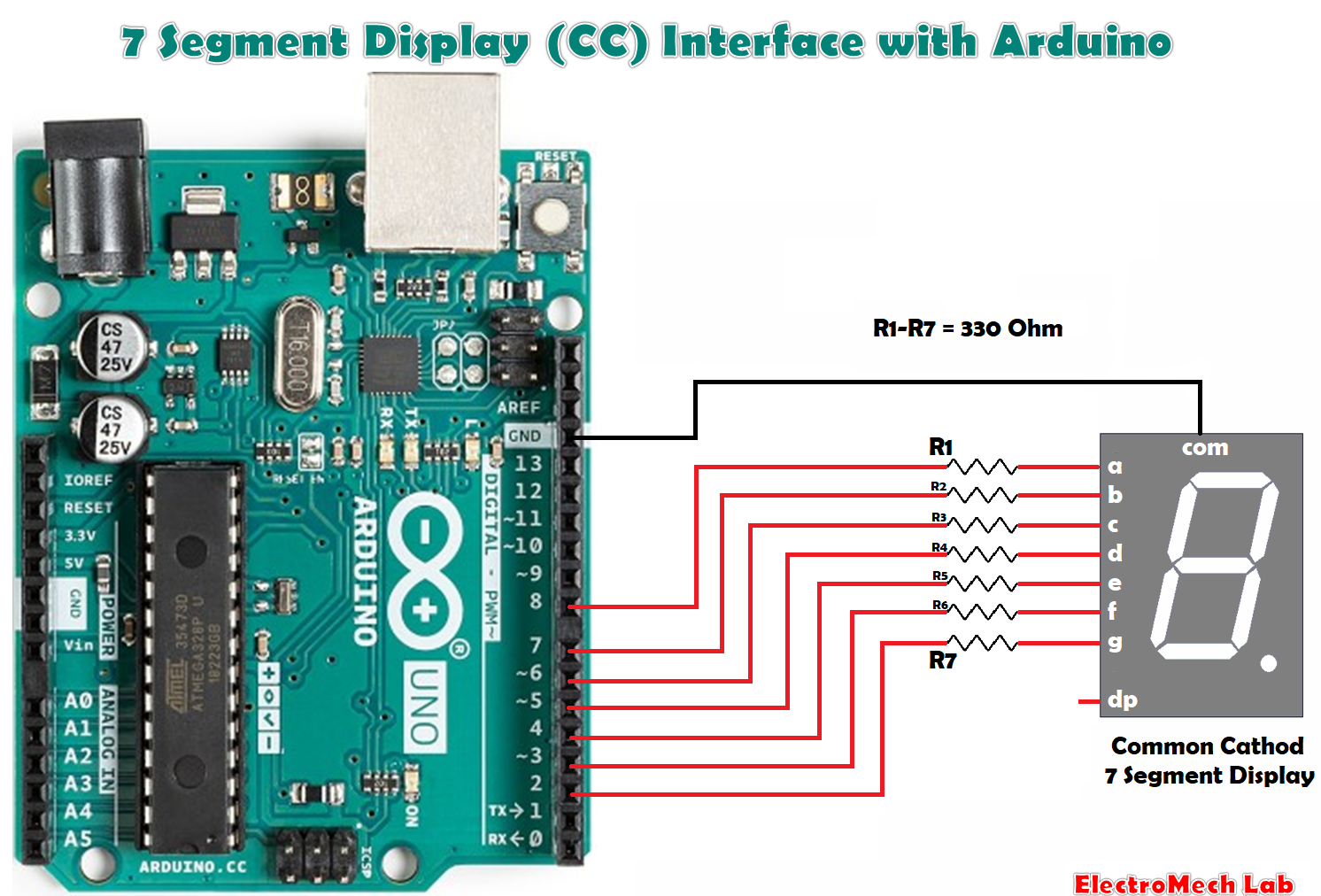
Seven-Segment Displays are used to
display the information; these are widely used in industries due to their
visibility and life.
There are two types of seven-segment
displays: common anode and common cathode. The Internal structure of each of
these types almost same. But, the polarity of the LEDs and common terminal are
different.
In most standard cathode
seven-segment, all seven LEDs, with a dot LED, have the cathodes connected to the
pins 3 and pin 8. To use it, we must connect GND to the pin 3 and pin 8, then
connect +5V to the other pins and make each of the individual segments glow.
The diagram below shows the internal structure of the common cathode
seven-segment display:
While, the common anode display is
opposite in respect of common connection. In a common anode display, the Anode
of the eight-shaped LEDs are connected together. They are then connected to pin
3 and pin 8. To glow an individual segment (LED), respective pin is to be
grounded. The diagram below shows the internal structure of the common anode
seven-segment display.
The dot is labelled as “dp”, while
the seven segments are labelled as a, b, c, d, e, f, g, as shown in the figure
below: