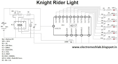
Material required for the circuit:
- IC 555 - 1 No.
- IC 4017 - 1 No.
- IN4001 Diode - 10 Nos.
- Red LED 5mm - 6 Nos.
- Resistor 1K/0.250W - 7 Nos.
- Resistor 100 Ohm/0.250W - 1 Nos.
- Variable resistor - 1 No.
- Disk capacitor 100nF - 1 No.
- Electrolytic Capacitor 22uF/25V - 1 No.
- Battery 9V - 1 No.
- Breadboard - 1 No.
- Wires for connection as required.
555 timer is working as an astable multivibrator which
supplies clocks to Counter IC 4017.
And on each clock its output gets high, one after one and
repeat this sequence till it gets input clock.
Make the connections according to the circuit diagram and
play with this very simple and easy circuit.
You are playing with the battery and capacitor so be aware of
their polarity.
These must be connected in proper polarity.

