The Simplest Electronics circuit.


Simplest Electronics circuit

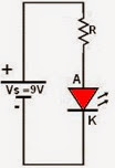
Hi guys, here is the simplest circuit; it is consisted of a resistor, an LED, and a battery.

Calculation is given below.

Vs: 9Vdc.

Voltage to the LED, let’s say 3Vdc,
Current through LED 20mA.
Through resistor voltage to be dropped: 9-3=6 Vdc.
Current through resistor: 20mA.
Resistor: V/I=6/20= 300 Ohm.
This is very simple circuit, can be easily assembled. So try it.
Normally is very simple for hobbyist and experienced circuit makers, but it can be a fun for new electronics hobbyist.

Collect the following components
One LED, 5mm size, one resistor of 300 Ohm, one 9V battery, and other tools like soldering iron, cutter, wire etc.
1- Connect resistor one end to the longer pin of LED with the help of solder (you can also connect them by twisting both the pins), Now we have two pins spare, one pin of resistor and another one is leg of LED.
2- Now connect the resistor spare end to the positive of battery and LED's to the negative of the battery. Now what do you see?
Is it glowing?
Yes?
So we have glowing LED now,
but the question is, we choose the resistor of 300 Ohm, why?
So we calculate the value.
3- There is a simple and most significant formula, Ohm's Law.
According to Ohm's law
I = V/R,
R=V/I,
V= I*R
I= Current (A) (current flowing through the resistor),
V= Voltage (V) (voltage across the resistor),
R= Resistance (Ohm).
In our circuit, we know…
The voltage supply voltage (Vs) = 9V.
Voltage across LED = 3V. (Normally LED 5mm runs on 3V).
Voltage dropped by resistance= 9-3=6V.
Current to be flowed through LED = 20mA = 0.020 Amp.
Resistance=?
Resistance= V/I = 6/0.020 = 300 Ohm.
NOTE: Dear friends I didn't have 330 Ohm at the time, so I used 470 Ohm.

You can control the brightness of LED by controlling the resistance value;
Resistance is to limit the current,

Warning

If you don't connect any resistance in series then current will be infinite and LED will be burnt immediately, So enjoy the circuit.


Comments

Popular posts from this blog

Difference between Bootloader & Firmware Update

Updating the bootloader and updating the firmware in a microcontroller are two distinct processes, each serving different purposes and involving different steps. Here's a breakdown of the differences: Bootloader Update Purpose : The bootloader is a small program that runs before the main application. It is responsible for initializing the microcontroller and loading the main application firmware. Updating the bootloader might be necessary to add new features, fix bugs, or improve the boot process.   Process : 1.       Enter Bootloader Mode : To update the bootloader, the microcontroller must be put into a special mode. This often involves setting specific pins, pressing buttons, or using a specific command through an existing firmware interface. 2.      Communication Interface : The bootloader update typically uses a specific communication interface such as UART, SPI, I2C, or USB. 3.   ...

AND Logic Gate by Transistors

Creating an AND gate using transistors is a fundamental exercise in digital electronics. In this post, I will guide you through the process of building an AND gate with transistors, explaining each step in detail.   What is an AND Gate? An AND gate is a basic digital logic gate that outputs TRUE or HIGH (1) only when all its inputs are true or high. If any of the inputs are false or low (0), the output is false or low (0). The truth table for a two-input AND gate is as follows: Input A Input B Output 0 0 0 0 1 0 1 0 0 1 1 1   Components Needed To build an AND gate, you will need the following components: NPN Transistors: BC547 (2 Nos.); Q1, Q2. Resistors : 10K (2 Nos) - R1, R2. Resistors : 1K (1 No) - R3. LED: 5mm Red (1 No) – L1, for output indication. Switches: ...

How to control Digital Output using Serial Monitor

Hello Friends, in this blog I will share with you how to control Arduino Digital Output with Serial Monitor. I am using One Arduino Uno, One 330 ohm resistor, One LED, 2 connecting cable, and one small Bread board. LED is connected to pin number 12, with the help of resistor 330 ohm. Below is the sketch: // Code by Deepak Sharma // The code is to control one digital output by serial monitor const int LED = 12; void setup() {   // put your setup code here, to run once:   Serial.begin(9600);   pinMode(LED, OUTPUT); } void loop() {   // put your main code here, to run repeatedly:   if (Serial.available()) {     String input = Serial.readStringUntil('\n');     input.trim();     if (input.equalsIgnoreCase("ON")) {       digitalWrite(LED, HIGH);       Serial.println("LED ON");     }     else if (input.equalsIgnoreCase("OFF")) {       digitalWrite(LED, LOW);     ...