How to Make Automatic Room Light Controller Without Microcontroller
You must have noticed in some offices or
hotels, when nobody is in gallery or washroom, the light remains OFF but when
somebody enters the place, light switches ON automatically.
In this post I am going to teach you how to
make this circuit.
Before going ahead I would like to tell you
that this is VERY EASY circuit.
For this circuit the material we need is…
PIR Motion sensor

General Purpose PCB - 5x5 cm.
Transistor 2222N – 1 No.
Relay 5V – 1 No.
1K/0.250W – 2 Nos.
10K/0.250W – 1 No.
IN4007 – 2 Nos.
LED 3mm – 1 No.
Connector – 4 Nos.
Few wires.
Relay Circuit

Concept: We can use any relay of 12V, 24V,
5V etc. but we have to consider power supply or battery we will use.
Since 5V power supply is easily available and
9V battery can also be used for 5V output (after using 7805 regulator if
needed).
So I am using 5V relay.
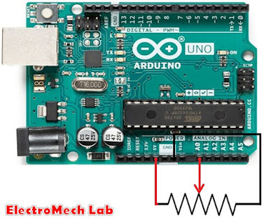
PIR sensor has three terminals,
One for 5Vdc
Second for Gnd (0V).
Third for output.
PIR sensor works as, when it senses
something presence then its output becomes high for the set time duration.
We will use this output to drive relay circuit.
Transistor 2222 is used, here, as a switch
to drive the relay though you can use any other NPN transistor.
Circuit description:


Connect 5Vdc to PIR sensor Vcc pin, Ground
(0V) to PIR sensor
Gnd pin.
5V is connected to the one end of the relay
and transistor collector is connected to the other end of the relay. So both
the ends of the relay have been connected.
Collector of transistor is connected.
Emitter of transistor is connected to the
0V (GND).
Now base of transistor is pulled down with
the help of 10K resistor, to avoid floating issue of its base pin.
One end of 1 Kohm resistor is connected to
the base, and input signal (driving signal) will be applied to other end of
1Kohm resistor.
Output of PIR sensor connected to the base
of transistor will conduct the transistor and coil of relay will be actuated
and contacts of relay will swap their postion.
COM (common) will connect to N/O.
I’ve connected one diode D2 across the
relay coil. It is working here as a free wheel diode. It can save the relay
from being damaged.
About free-wheel diode I will discuss in
another post.
I would like to mention here, whenever you connect any
diode in circuit BE ALERT!; you must be very well aware about their polarity.
NEVER connect diode in wrong polarity.
I have connected One LED to show the status of relay,
when relay is actuated, LED will glow, otherwise OFF.
1Kohm resistor is used in series with the LED.
I have added one IN4007 (I had only this, that’s why),
to positive line, to save this circuit from reverse power supply applied to the
circuit.
Now if you connect reverse voltage then circuit will
not damage.
Happy?
I tested this circuit with a 230vac bulb, you can also
try this.
Connect
the load in such a manner as shown in the picture.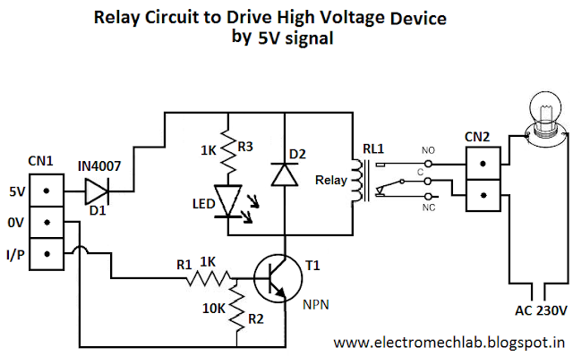
Thank you for very useful information.
ReplyDeleteChandeliers
I read that Post and got it fine and informative.
ReplyDeleteFlush Mount Lights
This is the type of information I’ve long been trying to find. Thank you for writing this information.
ReplyDeleteLustre