Posts

Showing posts from September, 2021

How to Decode Ceramic Capacitor Numeric Value

Image
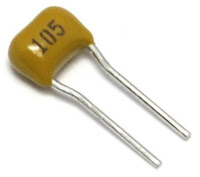
  Hello friends, ceramic capacitor are widely used in electronic circuit. But when it comes to know the value of the capacitor it becomes difficult sometimes, since on ceramic capacitor value is not written directly. There is a code on the capacitor and you have to decode that code to know the value.                                  So how can you know the value of ceramic capacitor? Before moving ahead get to know some units used in capacitor values. Unit of capacitor is Farad. But lower value of capacitors are used in circuits. First is Pico Farad, 1 pico is equal to 10 -12 Second is Nano Farad, 1 nano is equal to 10 -9 Third is Micro Farad, 1 micro is equal to 10 -6 A ceramic capacitor, usually, have 3 digit code, for example we have a capacitor having code 105. First 2 digits (1 & 0) are significant figures, and third one (5) is multiplier. Multiplier is considered with power of 10 as 10 5. After putting all values we have the value in pF (picoFarad) Pattern

How to Interface a 7-Segment Display with an Arduino?

Image
What is Seven-Segment Display? Seven-Segment Displays are used to display the information; these are widely used in industries due to their visibility and life. There are two types of seven-segment displays: common anode and common cathode. The Internal structure of each of these types almost same. But, the polarity of the LEDs and common terminal are different. In most standard cathode seven-segment, all seven LEDs, with a dot LED, have the cathodes connected to the pins 3 and pin 8. To use it, we must connect GND to the pin 3 and pin 8, then connect +5V to the other pins and make each of the individual segments glow. The diagram below shows the internal structure of the common cathode seven-segment display: While, the common anode display is opposite in respect of common connection. In a common anode display, the Anode of the eight-shaped LEDs are connected together. They are then connected to pin 3 and pin 8. To glow an individual segment (LED), respective pin is to b

How to Read Analog Input & Use PWM pin as Analog Output

Image
  Analog Input: An analog signal can take on any number of values. To measure the value of analog signals, Arduino has a built-in analog-to-digital converter (ADC). The ADC turns the analog voltage into a digital value. There is an inbuilt function to read Analog value; analogRead(pin_number). This function converts the value of the voltage on the analog input pin and returns a digital value ranges from 0 to 1023, relative to the reference value. The default reference voltage is 5 V (for 5 V Arduino boards) or 3.3 V (for 3.3 V Arduino boards). This function has only one parameter, which is the pin number.     Analog Output: The Arduino does not have any built-in digital-to-analog converter (DAC), but it can do pulse-width modulation (PWM); a digital signal to achieve some of the functions of an analog output. The function analogWrite(pin, value) is used to output a PWM signal. In the function ‘pin’ is the pin number used for the PWM output. ‘value’ is a number proportiona