What is Seven-Segment Display?

Seven-Segment Displays are used to
display the information; these are widely used in industries due to their
visibility and life.
There are two types of seven-segment
displays: common anode and common cathode. The Internal structure of each of
these types almost same. But, the polarity of the LEDs and common terminal are
different.
In most standard cathode
seven-segment, all seven LEDs, with a dot LED, have the cathodes connected to the
pins 3 and pin 8. To use it, we must connect GND to the pin 3 and pin 8, then
connect +5V to the other pins and make each of the individual segments glow.
The diagram below shows the internal structure of the common cathode
seven-segment display:

While, the common anode display is
opposite in respect of common connection. In a common anode display, the Anode
of the eight-shaped LEDs are connected together. They are then connected to pin
3 and pin 8. To glow an individual segment (LED), respective pin is to be
grounded. The diagram below shows the internal structure of the common anode
seven-segment display.

The dot is labelled as “dp”, while
the seven segments are labelled as a, b, c, d, e, f, g, as shown in the figure
below:

Experiment:
In
this experiment, we will learn how to connect a seven-segment display (CC type)
to an Arduino Uno.
Hardware Required
1
x 7-segment Display Common Cathode Type
7
x 330 ohm resistor
1
x Arduino UNO
1
x USB Cable
1
x breadboard
8
x jumper wires
You turn on the individual segments
to display a particular number, as seen in the following.
If you want to glow number 1, then
you need to power up segment ‘b’ and ‘c’.
For number two, glow the segments;
a, b, g, e, d.
For number three, glow the segments;
a, b, g, c, d.
For number four, glow the segments;
f, g, b, c.
For number five, glow the segments;
a, f, g, c, d
For number six, glow the segments;
f, g, e, d, c.
For number seven, glow the segments;
a, b, c.
For number eight, glow the segments;
a, b, c, d, e, f, g.
For number nine, glow the segments;
a, b, c, d, f, g.
For number point, glow the segment
dp.
So, that is about seven segment
display, now we will see how we connect SSD to the Arduino.
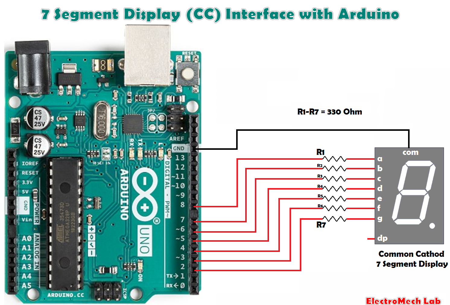
Make the connection between SSD and
Arduino as shown in the below picture.
Connect the pins, a, b, c, d, e, f,
g to the Arduino Pin numbers 8, 7, 6, 5, 4, 3, 2 respectively through resistors
330 ohm.
Connection common of SSD to the GND pin
of Arduino
Arduino Code:
#define SSD_a 8 // segment a
#define SSD_b 7 // segment b
#define SSD_c 6 // segment c
#define SSD_d 5 // segment d
#define SSD_e 4 // segment e
#define SSD_f 3 // segment f
#define SSD_g 2 // segment g
void setup()
{
pinMode (SSD_a, OUTPUT);
pinMode (SSD_b, OUTPUT);
pinMode (SSD_c, OUTPUT);
pinMode (SSD_d, OUTPUT);
pinMode (SSD_e, OUTPUT);
pinMode (SSD_f, OUTPUT);
pinMode (SSD_g, OUTPUT);
digitalWrite (SSD_a,LOW);
digitalWrite (SSD_b,LOW);
digitalWrite (SSD_c,LOW);
digitalWrite (SSD_d,LOW);
digitalWrite (SSD_e,LOW);
digitalWrite (SSD_f,LOW);
digitalWrite (SSD_g,LOW);
}
void loop()
{
SSD_0();
delay(1000);
SSD_1();
delay(1000);
SSD_2();
delay(1000);
SSD_3();
delay(1000);
SSD_4();
delay(1000);
SSD_5();
delay(1000);
SSD_6();
delay(1000);
SSD_7();
delay(1000);
SSD_8();
delay(1000);
SSD_9();
delay(1000);
}
void SSD_0()
{
digitalWrite (SSD_a, HIGH);
digitalWrite (SSD_b, HIGH);
digitalWrite (SSD_c, HIGH);
digitalWrite (SSD_d, HIGH);
digitalWrite (SSD_e, HIGH);
digitalWrite (SSD_f, HIGH);
digitalWrite (SSD_g, LOW);
}
void SSD_1()
{
digitalWrite (SSD_a, LOW);
digitalWrite (SSD_b, HIGH);
digitalWrite (SSD_c, HIGH);
digitalWrite (SSD_d, LOW);
digitalWrite (SSD_e, LOW);
digitalWrite (SSD_f, LOW);
digitalWrite (SSD_g, LOW);
}
void SSD_2()
{
digitalWrite (SSD_a, HIGH);
digitalWrite (SSD_b, HIGH);
digitalWrite (SSD_c, LOW);
digitalWrite (SSD_d, HIGH);
digitalWrite (SSD_e, HIGH);
digitalWrite (SSD_f, LOW);
digitalWrite (SSD_g, HIGH);
}
void SSD_3()
{
digitalWrite (SSD_a, HIGH);
digitalWrite (SSD_b, HIGH);
digitalWrite (SSD_c, HIGH);
digitalWrite (SSD_d, HIGH);
digitalWrite (SSD_e, LOW);
digitalWrite (SSD_f, LOW);
digitalWrite (SSD_g, HIGH);
}
void SSD_4()
{
digitalWrite (SSD_a, LOW);
digitalWrite (SSD_b, HIGH);
digitalWrite (SSD_c, HIGH);
digitalWrite (SSD_d, LOW);
digitalWrite (SSD_e, LOW);
digitalWrite (SSD_f, HIGH);
digitalWrite (SSD_g, HIGH);
}
void SSD_5()
{
digitalWrite (SSD_a, HIGH);
digitalWrite (SSD_b, LOW);
digitalWrite (SSD_c, HIGH);
digitalWrite (SSD_d, HIGH);
digitalWrite (SSD_e, LOW);
digitalWrite (SSD_f, HIGH);
digitalWrite (SSD_g, HIGH);
}
void SSD_6()
{
digitalWrite (SSD_a, HIGH);
digitalWrite (SSD_b, LOW);
digitalWrite (SSD_c, HIGH);
digitalWrite (SSD_d, HIGH);
digitalWrite (SSD_e, HIGH);
digitalWrite (SSD_f, HIGH);
digitalWrite (SSD_g, HIGH);
}
void SSD_7()
{
digitalWrite (SSD_a, HIGH);
digitalWrite (SSD_b, HIGH);
digitalWrite (SSD_c, HIGH);
digitalWrite (SSD_d, LOW);
digitalWrite (SSD_e, LOW);
digitalWrite (SSD_f, LOW);
digitalWrite (SSD_g, LOW);
}
void SSD_8()
{
digitalWrite (SSD_a, HIGH);
digitalWrite (SSD_b, HIGH);
digitalWrite (SSD_c, HIGH);
digitalWrite (SSD_d, HIGH);
digitalWrite (SSD_e, HIGH);
digitalWrite (SSD_f, HIGH);
digitalWrite (SSD_g, HIGH);
}
void SSD_9()
{
digitalWrite (SSD_a, HIGH);
digitalWrite (SSD_b, HIGH);
digitalWrite (SSD_c, HIGH);
digitalWrite (SSD_d, LOW);
digitalWrite (SSD_e, LOW);
digitalWrite (SSD_f, HIGH);
digitalWrite (SSD_g, HIGH);
}
Run the experiment
After
the connections, connect the Arduino to the PC using Arduino USB cable and transfer
the program to Arduino using Arduino IDE software.
USB
cable is also providing the power to the Arduino board so, no need to supply
separately to the Arduino.
Since
in the program we glowing the LEDs required for the digits 0-9, so it will show
the digits from 0 to 9 every second.