Analog
Input:
An analog signal can take on any number of values. To measure
the value of analog signals, Arduino has a built-in analog-to-digital converter
(ADC). The ADC turns the analog voltage into a digital value.
There is an inbuilt function to read Analog value;
analogRead(pin_number). This function converts the value of the voltage on the
analog input pin and returns a digital value ranges from 0 to 1023, relative to
the reference value. The default reference voltage is 5 V (for 5 V Arduino
boards) or 3.3 V (for 3.3 V Arduino boards). This function has only one
parameter, which is the pin number.
Analog
Output:
The Arduino does not have any built-in digital-to-analog
converter (DAC), but it can do pulse-width modulation (PWM); a digital signal
to achieve some of the functions of an analog output.
The function analogWrite(pin, value) is used to output a PWM
signal.
In the function ‘pin’ is the pin number used for the PWM
output. ‘value’ is a number proportional to the duty cycle of the signal.
When value is 0, then signal is always off. When value is
255, the signal is always on.
On Uno, Nano, Mini – PWM pins are 3, 5, 6, 9, 10, 11; PWM
Frequency is 490 Hz (Pin 5 & 6 : 980Hz)
On Mega- PWM Pins are 2-13, 44-46; PWM Frequency is
490 Hz (Pin 4 & 13: 980Hz)
For mapping an analog input value, which ranges from 0 to
1023 to a PWM output signal, which ranges from 0 - 255, there is an inbuilt
function ‘map(value, fromLow, fromHigh, toLow, toHigh)’. This function has five
parameters, one parameter is the variable in which the analog value is stored,
while the others are 0, 1023, 0 and 255 respectively.
Functions
The below options are Arduino functions associated with Analog
signals that we will use in this tutorial:
analogRead()
analogWrite()
Example:
Suppose you want to use pin no. A0 to sense any analog sensor,
then you will write the function as given below
analogRead (A0);
Experiment
1: Analog Value Read
In this experiment, we will read analog value on analog input
A0.
Hardware Required
1 x Potentiometer
1 x Arduino UNO
3 x Jumper wire
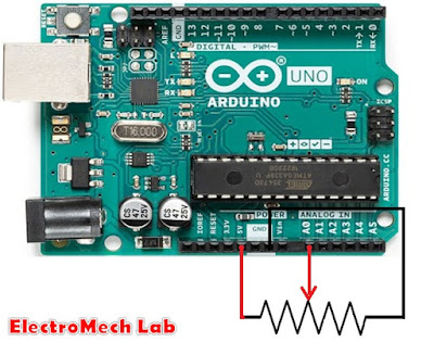
The figure above shows how to connect a potentiometer to
Arduino pin A0.
One corner terminal of POT is to be connected to the 5V of
Arduino and another corner pin of POT to be connected to GND.
Connect the middle pin of POT to A0.
Program
for Experiment #1
int inputAnalog = A0; // variable for analog input pin
int analogStatus = 0; // variable to save analog value
void setup()
{
Serial.begin(9600); // start the serial communication
}
void loop()
{
analogStatus = analogRead(inputAnalog); //Read the analog input value and save it in
the variable
Serial.println(analogStatus); //print the analog input value
on serial monitor
delay (1);
}
Run the experiment
Connect the POT to the Arduino as shown in the picture above.
Connect the Arduino to the PC using Arduino USB cable and
transfer the program to Arduino using Arduino IDE software.
USB cable is also providing the power to the Arduino board
so, no need to supply separately to the Arduino.
Rotate the knob of the POT to change the voltage at pin A0.
You can see the value on the Serial communication as shown
below
Experiment
2: Use PWM pin as Analog Output
This experiment will demonstrate how to use a PWM pin as
Analog Output.
For mapping an analog input value, which ranges from 0 to
1023 to a PWM output signal, which ranges from 0 - 255, there is an inbuilt
function ‘map(value, fromLow, fromHigh, toLow, toHigh)’. This function has five
parameters, one parameter is the variable in which the analog value is stored,
while the others are 0, 1023, 0 and 255 respectively.
Hardware Required
1 x LED
1 x 330 ohm resistor
1x Bread Board
1 x Arduino UNO
2 x jumper Wires
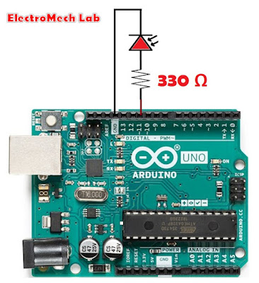
As you can see from the diagram above, we are now using one
Arduino PWM Pin 11. An LED is connected to pin 11, through a resistor of 330
Ohm value, which is a PWM Pin. When we
write the value on PWM pin corresponding to the value brightness of the LED
changes.
Program
for Experiment #2
#define outputAnalog 11 // define constant for PWM pin
#define delay1 1000 // define constant for delay
void setup()
{
pinMode(outputAnalog,OUTPUT);
analogWrite(outputAnalog,0);
}
void loop()
{
analogWrite(outputAnalog,0);
delay(delay1);
analogWrite(outputAnalog,50);
delay(delay1);
analogWrite(outputAnalog,100);
delay(delay1);
analogWrite(outputAnalog,150);
delay(delay1);
analogWrite(outputAnalog,200);
delay(delay1);
analogWrite(outputAnalog,255);
delay(delay1);
}
Run the experiment
Connect the circuit as shown in the above diagram.
Connect the Arduino to the PC using Arduino USB cable and
transfer the program to Arduino using Arduino IDE software.
USB cable is providing also providing the power to the
Arduino so, no need to provide the power separately.
As program runs continuously brightness changes.


