How to Decode Ceramic Capacitor Numeric Value


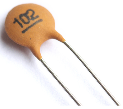
Hello friends, ceramic capacitor are widely used in electronic circuit. But when it comes to know the value of the capacitor it becomes difficult sometimes, since on ceramic capacitor value is not written directly. There is a code on the capacitor and you have to decode that code to know the value.


So how can you know the value of ceramic capacitor? Before moving ahead get to know some units used in capacitor values.

Unit of capacitor is Farad. But lower value of capacitors are used in circuits.

First is Pico Farad, 1 pico is equal to 10-12

Second is Nano Farad, 1 nano is equal to 10-9

Third is Micro Farad, 1 micro is equal to 10-6

A ceramic capacitor, usually, have 3 digit code, for example we have a capacitor having code 105.

First 2 digits (1 & 0) are significant figures, and third one (5) is multiplier. Multiplier is considered with power of 10 as 105.

After putting all values we have the value in pF (picoFarad)

Pattern of to decode the value

First Figure   Second Figure  x 10multiplier

Value is in pF

Let’s decode the code

Marking on capacitor ‘105’

Pattern to decode, 10 x 105 = 1000000 pF

Now we have the value in pF, we can change it into nF by multiplying it by 10-3. Since, It is in pF, which is equal to  10-12 and we are changing it into nF which is equal to 10-9, difference in these multiplier is of 3.

After multiplying it by 10-3 We have value in nF

= 1000000 x 10-3 nF =1000 nF

But if you want value in micro Farad (μF) then multiply it by 10-6.

= 1000000 x 10-6 μF =1 μF


How to Interface a 7-Segment Display with an Arduino?


What is Seven-Segment Display?


Seven-Segment Displays are used to display the information; these are widely used in industries due to their visibility and life.

There are two types of seven-segment displays: common anode and common cathode. The Internal structure of each of these types almost same. But, the polarity of the LEDs and common terminal are different.

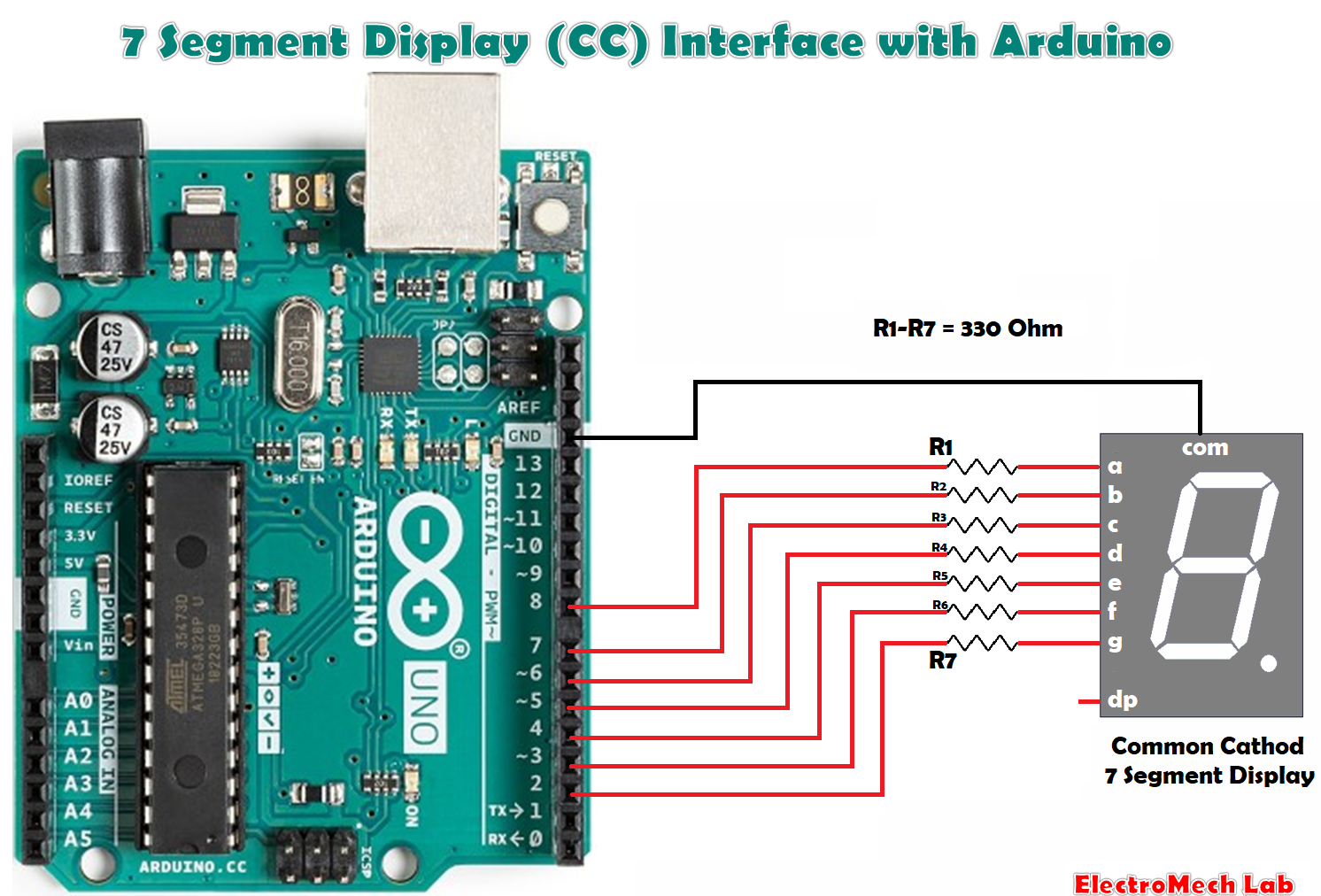
In most standard cathode seven-segment, all seven LEDs, with a dot LED, have the cathodes connected to the pins 3 and pin 8. To use it, we must connect GND to the pin 3 and pin 8, then connect +5V to the other pins and make each of the individual segments glow. The diagram below shows the internal structure of the common cathode seven-segment display:


While, the common anode display is opposite in respect of common connection. In a common anode display, the Anode of the eight-shaped LEDs are connected together. They are then connected to pin 3 and pin 8. To glow an individual segment (LED), respective pin is to be grounded. The diagram below shows the internal structure of the common anode seven-segment display. 


The dot is labelled as “dp”, while the seven segments are labelled as a, b, c, d, e, f, g, as shown in the figure below:


Experiment:

In this experiment, we will learn how to connect a seven-segment display (CC type) to an Arduino Uno.


Hardware Required

1 x 7-segment Display Common Cathode Type

7 x 330 ohm resistor

1 x Arduino UNO

1 x USB Cable

1 x breadboard

8 x jumper wires

You turn on the individual segments to display a particular number, as seen in the following.

If you want to glow number 1, then you need to power up segment ‘b’ and ‘c’.

For number two, glow the segments; a, b, g, e, d.

For number three, glow the segments; a, b, g, c, d.

For number four, glow the segments; f, g, b, c.

For number five, glow the segments; a, f, g, c, d

For number six, glow the segments; f, g, e, d, c.

For number seven, glow the segments; a, b, c.

For number eight, glow the segments; a, b, c, d, e, f, g.

For number nine, glow the segments; a, b, c, d, f, g.

For number point, glow the segment dp.


So, that is about seven segment display, now we will see how we connect SSD to the Arduino.

Make the connection between SSD and Arduino as shown in the below picture.

Connect the pins, a, b, c, d, e, f, g to the Arduino Pin numbers 8, 7, 6, 5, 4, 3, 2 respectively through resistors 330 ohm.

Connection common of SSD to the GND pin of Arduino


 Make the connections as shown in the above picture.

Arduino Code:

#define SSD_a 8 // segment a

#define SSD_b 7 // segment b

#define SSD_c 6 // segment c

#define SSD_d 5 // segment d

#define SSD_e 4 // segment e

#define SSD_f 3 // segment f

#define SSD_g 2 // segment g


void setup()

{

pinMode (SSD_a, OUTPUT);

pinMode (SSD_b, OUTPUT);

pinMode (SSD_c, OUTPUT);

pinMode (SSD_d, OUTPUT);

pinMode (SSD_e, OUTPUT);

pinMode (SSD_f, OUTPUT);

pinMode (SSD_g, OUTPUT);


digitalWrite (SSD_a,LOW);

digitalWrite (SSD_b,LOW);

digitalWrite (SSD_c,LOW);

digitalWrite (SSD_d,LOW);

digitalWrite (SSD_e,LOW);

digitalWrite (SSD_f,LOW);

digitalWrite (SSD_g,LOW);

}


void loop()

{

SSD_0();

delay(1000);

SSD_1();

delay(1000);

SSD_2();

delay(1000);

SSD_3();

delay(1000);

SSD_4();

delay(1000);

SSD_5();

delay(1000);

SSD_6();

delay(1000);

SSD_7();

delay(1000);

SSD_8();

delay(1000);

SSD_9();

delay(1000);

}


void SSD_0()

{

digitalWrite (SSD_a, HIGH);

digitalWrite (SSD_b, HIGH);

digitalWrite (SSD_c, HIGH);

digitalWrite (SSD_d, HIGH);

digitalWrite (SSD_e, HIGH);

digitalWrite (SSD_f, HIGH);

digitalWrite (SSD_g, LOW);

}


void SSD_1()

{

digitalWrite (SSD_a, LOW);

digitalWrite (SSD_b, HIGH);

digitalWrite (SSD_c, HIGH);

digitalWrite (SSD_d, LOW);

digitalWrite (SSD_e, LOW);

digitalWrite (SSD_f, LOW);

digitalWrite (SSD_g, LOW);

}


void SSD_2()

{

digitalWrite (SSD_a, HIGH);

digitalWrite (SSD_b, HIGH);

digitalWrite (SSD_c, LOW);

digitalWrite (SSD_d, HIGH);

digitalWrite (SSD_e, HIGH);

digitalWrite (SSD_f, LOW);

digitalWrite (SSD_g, HIGH);

}


void SSD_3()

{

digitalWrite (SSD_a, HIGH);

digitalWrite (SSD_b, HIGH);

digitalWrite (SSD_c, HIGH);

digitalWrite (SSD_d, HIGH);

digitalWrite (SSD_e, LOW);

digitalWrite (SSD_f, LOW);

digitalWrite (SSD_g, HIGH);

}


void SSD_4()

{

digitalWrite (SSD_a, LOW);

digitalWrite (SSD_b, HIGH);

digitalWrite (SSD_c, HIGH);

digitalWrite (SSD_d, LOW);

digitalWrite (SSD_e, LOW);

digitalWrite (SSD_f, HIGH);

digitalWrite (SSD_g, HIGH);

}


void SSD_5()

{

digitalWrite (SSD_a, HIGH);

digitalWrite (SSD_b, LOW);

digitalWrite (SSD_c, HIGH);

digitalWrite (SSD_d, HIGH);

digitalWrite (SSD_e, LOW);

digitalWrite (SSD_f, HIGH);

digitalWrite (SSD_g, HIGH);

}


void SSD_6()

{

digitalWrite (SSD_a, HIGH);

digitalWrite (SSD_b, LOW);

digitalWrite (SSD_c, HIGH);

digitalWrite (SSD_d, HIGH);

digitalWrite (SSD_e, HIGH);

digitalWrite (SSD_f, HIGH);

digitalWrite (SSD_g, HIGH);

}


void SSD_7()

{

digitalWrite (SSD_a, HIGH);

digitalWrite (SSD_b, HIGH);

digitalWrite (SSD_c, HIGH);

digitalWrite (SSD_d, LOW);

digitalWrite (SSD_e, LOW);

digitalWrite (SSD_f, LOW);

digitalWrite (SSD_g, LOW);

}


void SSD_8()

{

digitalWrite (SSD_a, HIGH);

digitalWrite (SSD_b, HIGH);

digitalWrite (SSD_c, HIGH);

digitalWrite (SSD_d, HIGH);

digitalWrite (SSD_e, HIGH);

digitalWrite (SSD_f, HIGH);

digitalWrite (SSD_g, HIGH);

}


void SSD_9()

{

digitalWrite (SSD_a, HIGH);

digitalWrite (SSD_b, HIGH);

digitalWrite (SSD_c, HIGH);

digitalWrite (SSD_d, LOW);

digitalWrite (SSD_e, LOW);

digitalWrite (SSD_f, HIGH);

digitalWrite (SSD_g, HIGH);

}


Run the experiment

After the connections, connect the Arduino to the PC using Arduino USB cable and transfer the program to Arduino using Arduino IDE software.

USB cable is also providing the power to the Arduino board so, no need to supply separately to the Arduino.

Since in the program we glowing the LEDs required for the digits 0-9, so it will show the digits from 0 to 9 every second.


How to Read Analog Input & Use PWM pin as Analog Output


Analog Input:

An analog signal can take on any number of values. To measure the value of analog signals, Arduino has a built-in analog-to-digital converter (ADC). The ADC turns the analog voltage into a digital value.

There is an inbuilt function to read Analog value; analogRead(pin_number). This function converts the value of the voltage on the analog input pin and returns a digital value ranges from 0 to 1023, relative to the reference value. The default reference voltage is 5 V (for 5 V Arduino boards) or 3.3 V (for 3.3 V Arduino boards). This function has only one parameter, which is the pin number.


Analog Output:

The Arduino does not have any built-in digital-to-analog converter (DAC), but it can do pulse-width modulation (PWM); a digital signal to achieve some of the functions of an analog output.

The function analogWrite(pin, value) is used to output a PWM signal.

In the function ‘pin’ is the pin number used for the PWM output. ‘value’ is a number proportional to the duty cycle of the signal.

When value is 0, then signal is always off. When value is 255, the signal is always on.

On Uno, Nano, Mini – PWM pins are 3, 5, 6, 9, 10, 11; PWM Frequency is 490 Hz (Pin 5 & 6 : 980Hz)

On Mega- PWM Pins are 2-13, 44-46; PWM Frequency is 490 Hz (Pin 4 & 13: 980Hz)

For mapping an analog input value, which ranges from 0 to 1023 to a PWM output signal, which ranges from 0 - 255, there is an inbuilt function ‘map(value, fromLow, fromHigh, toLow, toHigh)’. This function has five parameters, one parameter is the variable in which the analog value is stored, while the others are 0, 1023, 0 and 255 respectively.

Functions

The below options are Arduino functions associated with Analog signals that we will use in this tutorial:

analogRead()

analogWrite()


Example:

Suppose you want to use pin no. A0 to sense any analog sensor, then you will write the function as given below

analogRead (A0);


Experiment 1: Analog Value Read

In this experiment, we will read analog value on analog input A0.

Hardware Required

1 x Potentiometer

1 x Arduino UNO

3 x Jumper wire


The figure above shows how to connect a potentiometer to Arduino pin A0.

One corner terminal of POT is to be connected to the 5V of Arduino and another corner pin of POT to be connected to GND.

Connect the middle pin of POT to A0.


Program for Experiment #1

int inputAnalog = A0; // variable for analog input pin

int analogStatus = 0; // variable to save analog value


void setup()

{

Serial.begin(9600); // start the serial communication

}


void loop()

{

analogStatus = analogRead(inputAnalog);  //Read the analog input value and save it in the variable

Serial.println(analogStatus); //print the analog input value on serial monitor

delay (1);

}


Run the experiment

Connect the POT to the Arduino as shown in the picture above.

Connect the Arduino to the PC using Arduino USB cable and transfer the program to Arduino using Arduino IDE software.

USB cable is also providing the power to the Arduino board so, no need to supply separately to the Arduino.

Rotate the knob of the POT to change the voltage at pin A0.

You can see the value on the Serial communication as shown below


Experiment 2: Use PWM pin as Analog Output

This experiment will demonstrate how to use a PWM pin as Analog Output.

For mapping an analog input value, which ranges from 0 to 1023 to a PWM output signal, which ranges from 0 - 255, there is an inbuilt function ‘map(value, fromLow, fromHigh, toLow, toHigh)’. This function has five parameters, one parameter is the variable in which the analog value is stored, while the others are 0, 1023, 0 and 255 respectively.


Hardware Required

1 x LED

1 x 330 ohm resistor

1x Bread Board

1 x Arduino UNO

2 x jumper Wires


As you can see from the diagram above, we are now using one Arduino PWM Pin 11. An LED is connected to pin 11, through a resistor of 330 Ohm value, which is a PWM Pin.  When we write the value on PWM pin corresponding to the value brightness of the LED changes.


Program for Experiment #2

#define outputAnalog 11 // define constant for PWM pin

#define delay1 1000 // define constant for delay


void setup()

{

pinMode(outputAnalog,OUTPUT);

analogWrite(outputAnalog,0);

}


void loop()

{

analogWrite(outputAnalog,0);

delay(delay1);

analogWrite(outputAnalog,50);

delay(delay1);

analogWrite(outputAnalog,100);

delay(delay1);

analogWrite(outputAnalog,150);

delay(delay1);

analogWrite(outputAnalog,200);

delay(delay1);

analogWrite(outputAnalog,255);

delay(delay1);

}


Run the experiment

Connect the circuit as shown in the above diagram.

Connect the Arduino to the PC using Arduino USB cable and transfer the program to Arduino using Arduino IDE software.

USB cable is providing also providing the power to the Arduino so, no need to provide the power separately.

As program runs continuously brightness changes.